In my previous blog about Maix Bit, we covered camera sensor, lcd display, and SPI with logic analyzer. However, WiFi is NEVER talked about.
1. Cable Connection
1.1 Pin Definitions of ESP32-C3 Super Mini
Cited from First Look at the Super Mini ESP32-C3:
![]()
1.2 Sipeed MaixBit Datasheet
Please refer to:
The key thing to keep in mind is: pin 26, 27, 28, 29 are reserved for TF card by default. Cited from Sipeed MaixBit Datasheet V2.0 as:
| Maix Bit V2.0 Slik | K210 IO | Function | Remark |
|---|---|---|---|
| 26 | IO26 | SPI0_MISO | Reserved for TF Card |
| 27 | IO27 | SPI0_SCLK | Reserved for TF Card |
| 28 | IO28 | SPI0_MOSI | Reserved for TF Card |
| 29 | IO29 | SPI0_CS0 | Reserved for TF Card |
Therefore, in my test, I’m going to use the pins 22,23,24,25 and 21 (optional) instead, and summarized in the NEXT section.
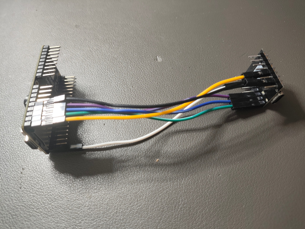
1.3 Wired Connection Between Maix Bit board and ESP32-C3 Super Mini
| Signal | Maix Bit | Direction | ESP32-C3 Super Mini | Description | Typical Wire Color | Notes |
|---|---|---|---|---|---|---|
| GND | GND | Shared | GND | Ground reference | Black | Must be common between boards |
| SCLK (SCK) | 22 | ==> | 4 | SPI clock | yellow | Clock lines are often yellow |
| MISO | 23 | <== | 5 | Master In, Slave Out | green | Data from ESP32-C3 Super Mini to MaixBit |
| MOSI | 24 | ==> | 6 | Master Out, Slave In | blue | Data from MaixBit to ESP32-C3 Super Mini |
| CS (SS) | 25 | ==> | 7 | Chip Select (active low) | white | One CS per SPI slave |
| RDY | 21 | <== | 10 | Ready / Flow-control signal | purple | Optional but recommended |
2. Hardware Info
2.1 lsusb
1 | Bus 009 Device 033: ID 303a:1001 Espressif USB JTAG/serial debug unit |
2.2 kflash and esptool
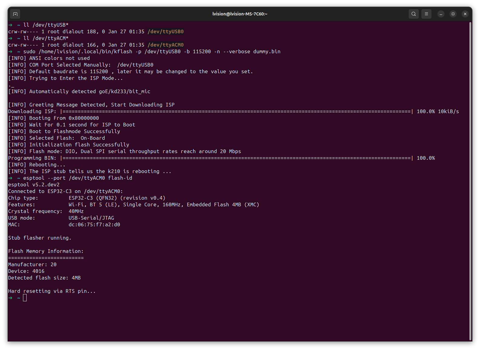
Clearly,
/dev/ttyUSB0: Maix Bit/dev/ttyACM0: ESP32-C3 Super Mini
3. Flash
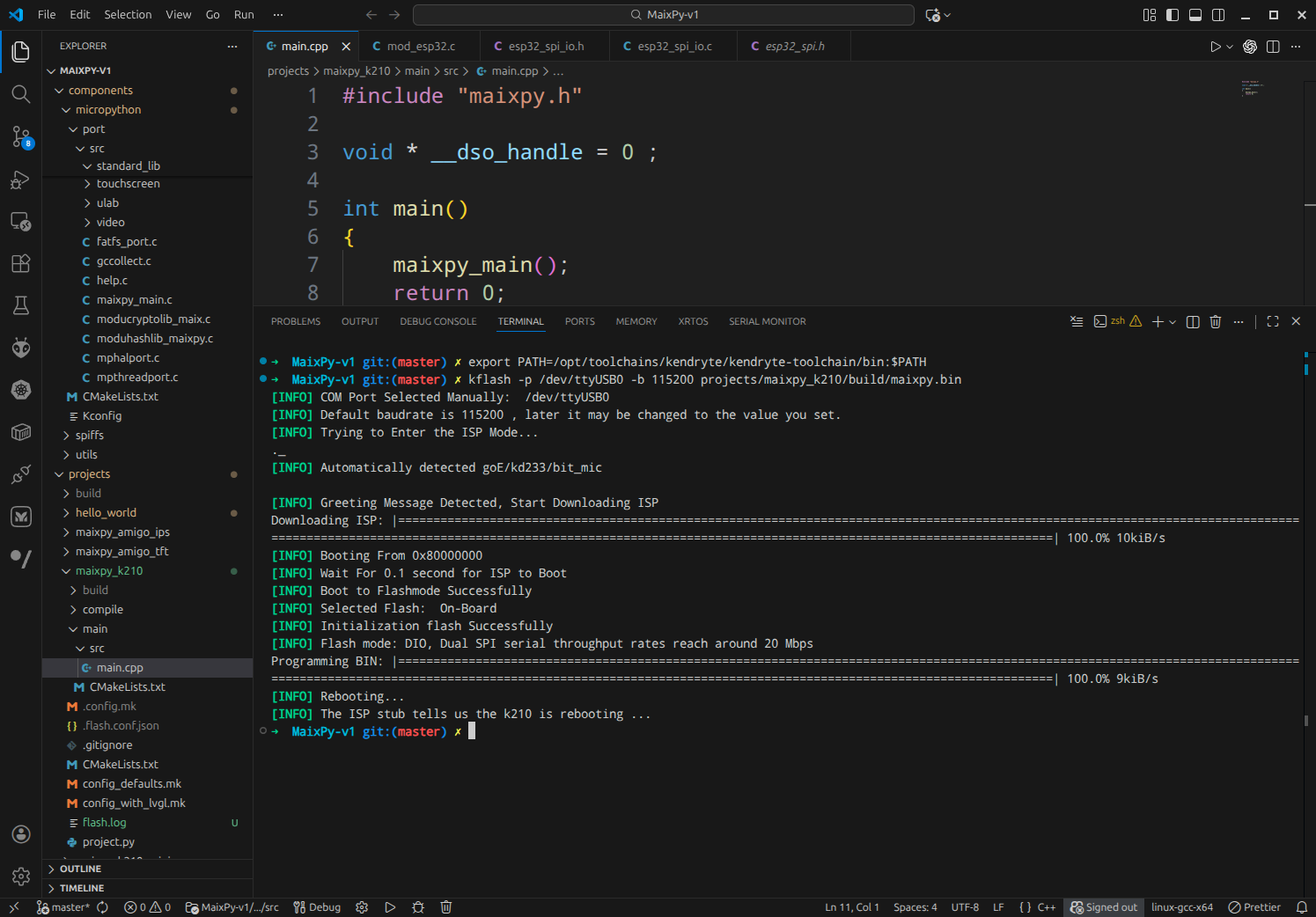
3.1 kflash MaixPy-v1 onto Maix Bit
3.2 esptool onto ESP32-C3 Super Mini
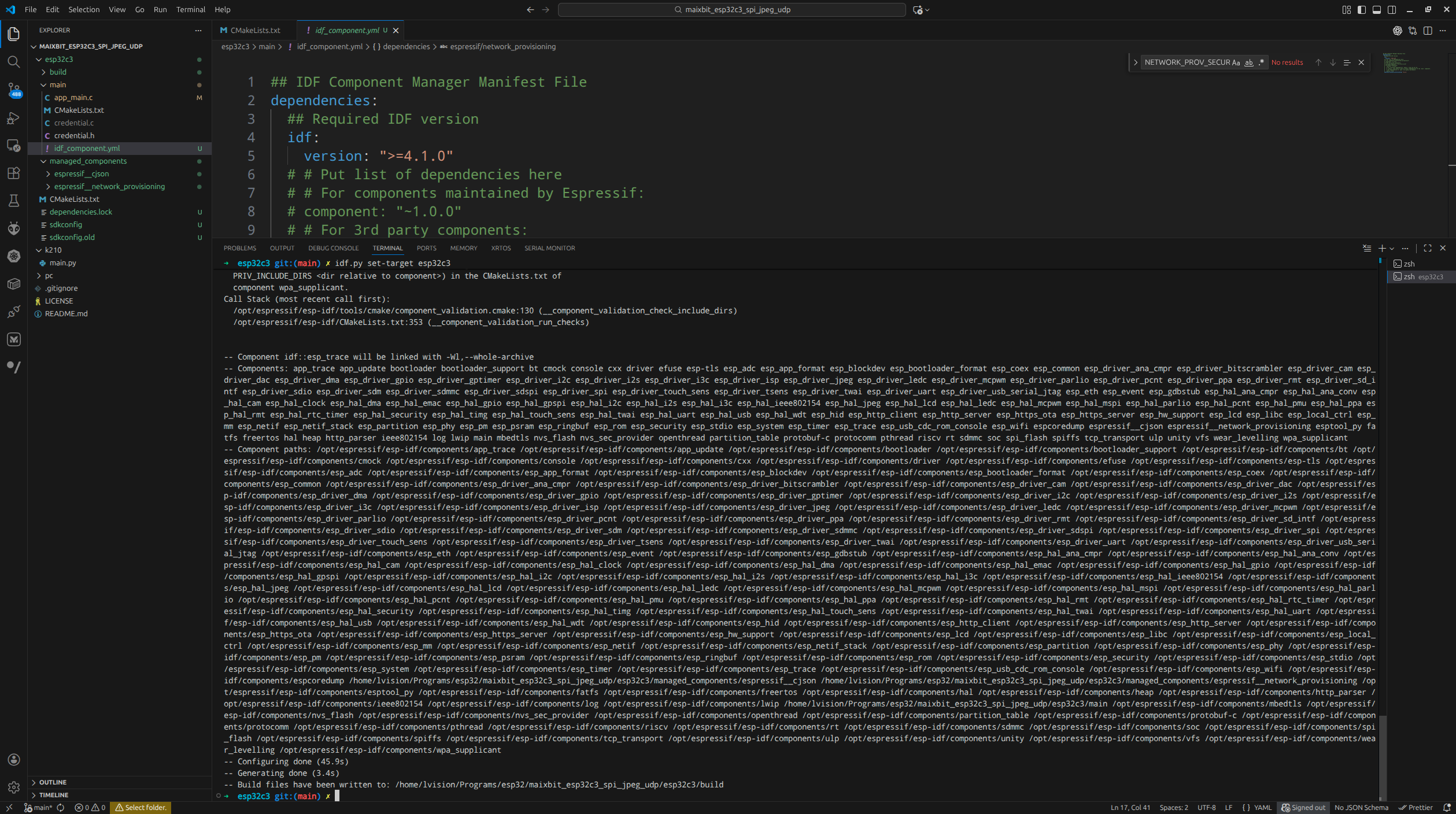
idf.py set-target esp32c3 |
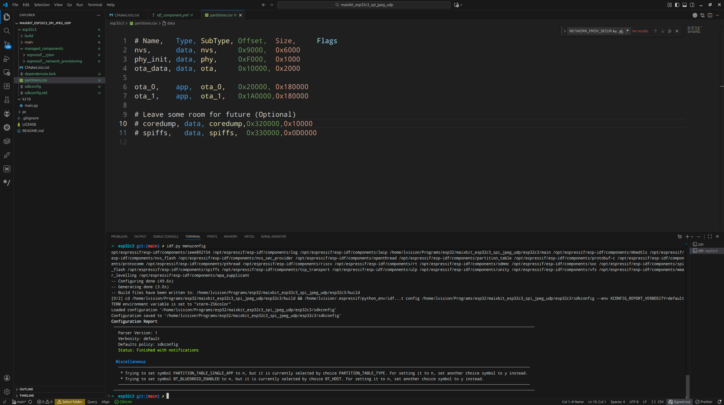
partitions.csv |
|---|---|
 |
 |
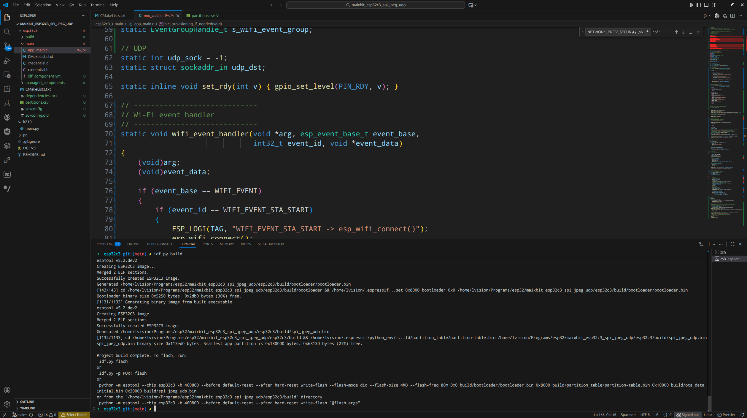
idf.py build |
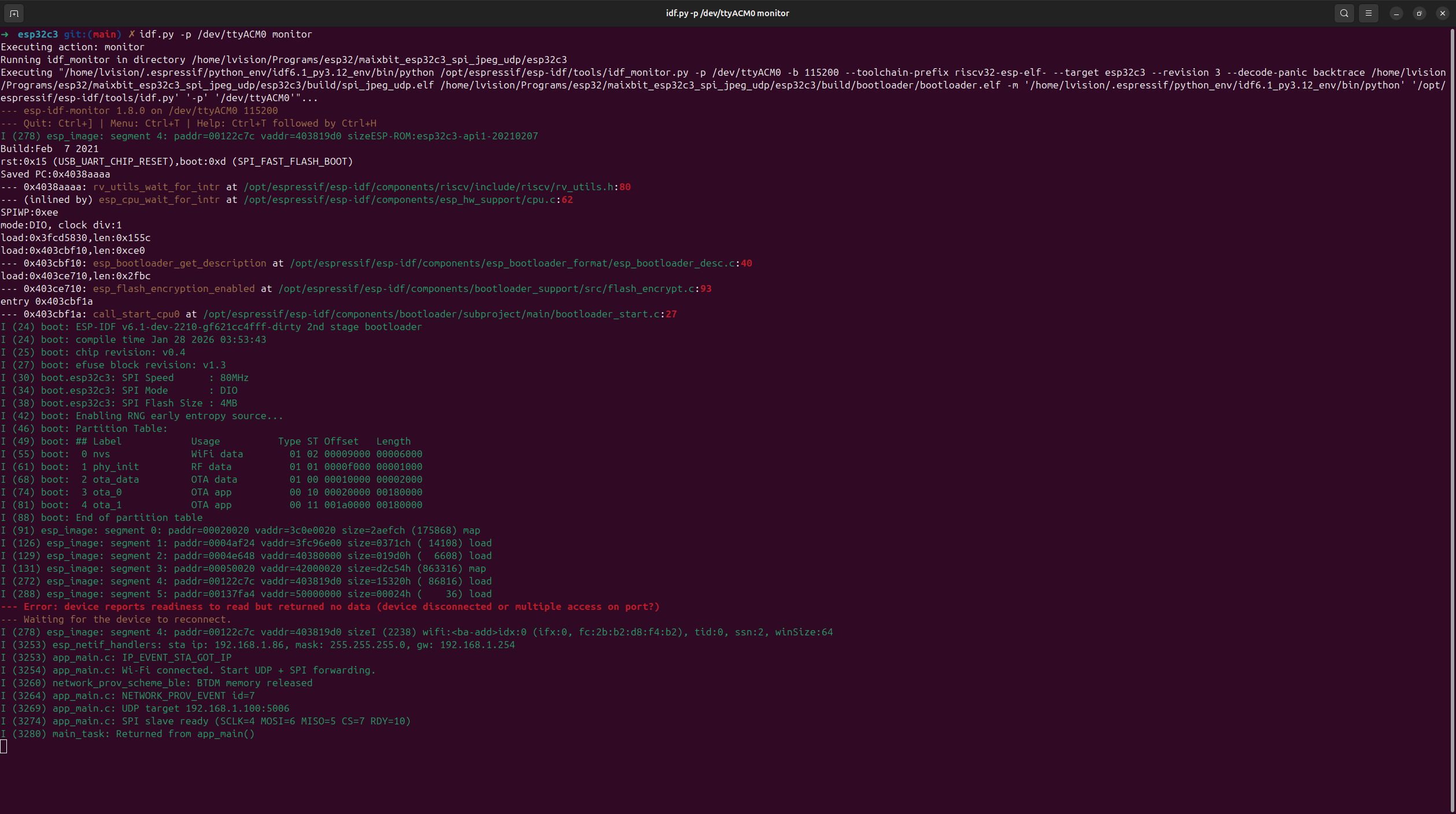
flash and monitor |
|---|---|
 |
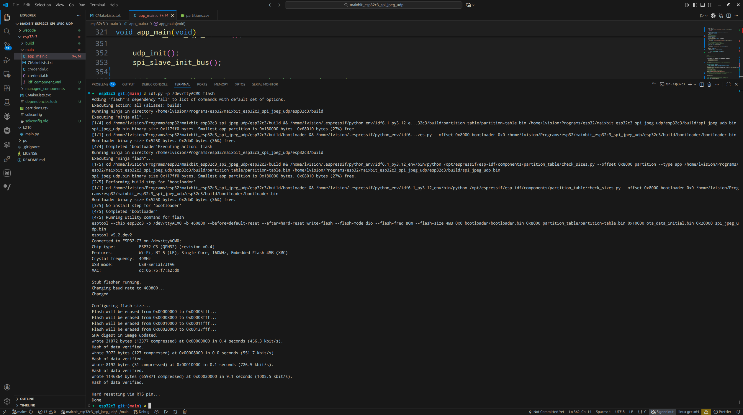 |