AttributeError: type object ‘Path’ has no attribute ‘home’
This error message is found while I was trying to from matplotlib.pyplot as plt today. I’ve got NO idea what had happened to my python. But, it seems this issue had been met and solved in some public posts. For instance:
After having successfully installed PyTorch current version 1.1, I still failed to import torch. Please refer to the following ERROR.
1 2 3 4 5 6 7 8 9 10 11 12 13 14 15 16 17
➜ ~ python Python 3.6.7 (default, Oct 22 2018, 11:32:17) [GCC 8.2.0] on linux Type "help", "copyright", "credits" or "license" for more information. >>> import torch Traceback (most recent call last): File "<stdin>", line 1, in <module> File "~/.local/lib/python3.6/site-packages/torch/__init__.py", line 84, in <module> from torch._C import * ImportError: ~/.local/lib/python3.6/site-packages/torch/lib/libcaffe2.so: undefined symbol: _ZTIN3c1010TensorImplE >>> import caffe2 >>> caffe2.__version__ Traceback (most recent call last): File "<stdin>", line 1, in <module> AttributeError: module 'caffe2' has no attribute '__version__' >>> caffe2.__file__ '~/.local/lib/python3.6/site-packages/caffe2/__init__.py'
In order to have PyTorch successully imported, I’ve got to remove the manually installed PyTorch v 1.1, but had it installed by pip
This is PyTorch v1.0, which seems NOT come with caffe2, and of course should NOT be compatible with the installed caffe2 built with PyTorch v1.1. Can anybody help to solve this issue? Please also refer to Github issue.
Solution
Remove anything/everything related to your previously installed PyTorch. In my case, file /usr/local/lib/libc10.s0 is to be removed. In order to analyze which files are possibly related to the concerned package, we can use the command ldd.
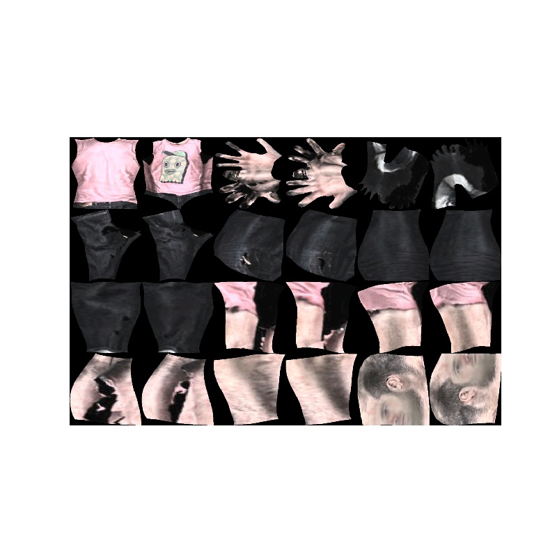
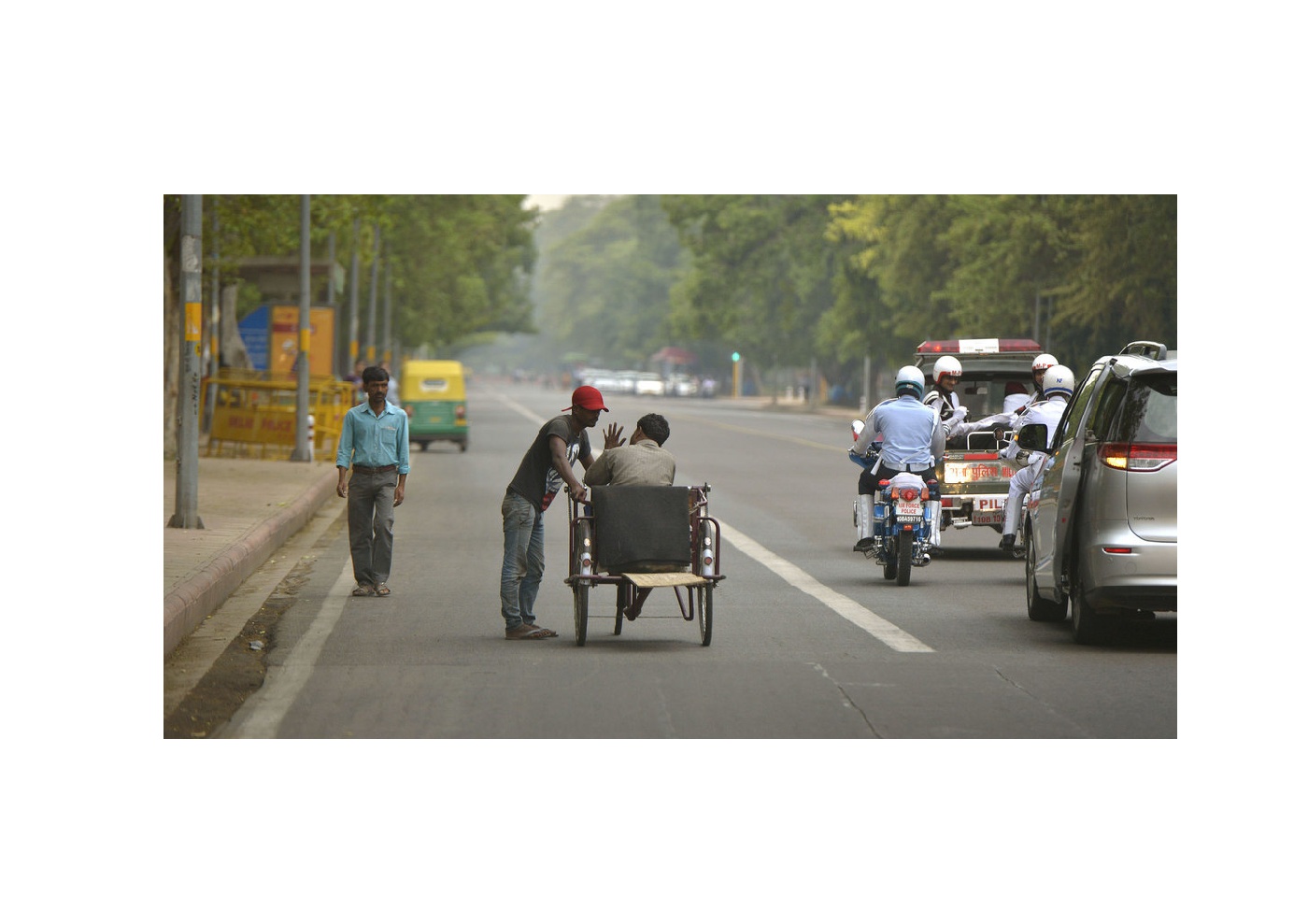
It’s not hard to have FlowNet2-Pytorch installed by one line of commands:
1
➜ flownet2-pytorch git:(master) ✗ ./install.sh
After installation, there will be 3 packages installed under folder ~/.local/lib/python3.6/site-packages:
correlation-cuda
resample2d-cuda
channelnorm-cuda
1 2 3 4 5 6 7 8 9 10
➜ site-packages ls -lsd correlation* 4 drwxrwxr-x 4 jiapei jiapei 4096 Jan 7 00:07 correlation_cuda-0.0.0-py3.6-linux-x86_64.egg ➜ site-packages ls -lsd channelnorm* 4 drwxrwxr-x 4 jiapei jiapei 4096 Jan 7 00:07 channelnorm_cuda-0.0.0-py3.6-linux-x86_64.egg ➜ site-packages ls -lsd resample2d* 4 drwxrwxr-x 4 jiapei jiapei 4096 Jan 7 00:07 resample2d_cuda-0.0.0-py3.6-linux-x86_64.egg ➜ site-packages ls -lsd flownet2* zsh: no matches found: flownet2* ➜ site-packages pwd ~/.local/lib/python3.6/site-packages
That is to say: you should NEVER import flownet2, nor correlation, nor channelnorm, nor resampled2d, but
correlation_cuda
resample2d_cuda
channelnorm_cuda
Current Bug
Here comes the ERROR:
1
2
3
4
5
6
7
8
9
10
11
12
13
14
15
16
17
➜ ~ python Python 3.6.7 (default, Oct 22 2018, 11:32:17) [GCC 8.2.0] on linux Type "help", "copyright", "credits" or "license" for more information. >>> import correlation_cuda Traceback (most recent call last): File "<stdin>", line 1, in <module> ImportError: ~/.local/lib/python3.6/site-packages/correlation_cuda-0.0.0-py3.6-linux-x86_64.egg/correlation_cuda.cpython-36m-x86_64-linux-gnu.so: undefined symbol: _ZN2at19UndefinedTensorImpl10_singletonE >>> import channelnorm_cuda Traceback (most recent call last): File "<stdin>", line 1, in <module> ImportError: ~/.local/lib/python3.6/site-packages/channelnorm_cuda-0.0.0-py3.6-linux-x86_64.egg/channelnorm_cuda.cpython-36m-x86_64-linux-gnu.so: undefined symbol: _ZN2at19UndefinedTensorImpl10_singletonE >>> import resample2d_cuda Traceback (most recent call last): File "<stdin>", line 1, in <module> ImportError: ~/.local/lib/python3.6/site-packages/resample2d_cuda-0.0.0-py3.6-linux-x86_64.egg/resample2d_cuda.cpython-36m-x86_64-linux-gnu.so: undefined symbol: _ZN2at19UndefinedTensorImpl10_singletonE >>>
I’ve already posted an issue on github. Had anybody solved this problem?
Solution
import torch FIRST.
1 2 3 4 5 6 7 8
➜ ~ python Python 3.6.7 (default, Oct 22 2018, 11:32:17) [GCC 8.2.0] on linux Type "help", "copyright", "credits" or "license" for more information. >>> import torch >>> import correlation_cuda >>> import resample2d_cuda >>> import channelnorm_cuda
Source Code Current Git Hash: b'ac1602a72f0454f65872126b70665a596fae8009'
Initializing Datasets [0.003s] Operation failed
Traceback (most recent call last): File "main.py", line 139, in <module> train_dataset = args.training_dataset_class(args, True, **tools.kwargs_from_args(args, 'training_dataset')) File "....../flownet2-pytorch/datasets.py", line 112, in __init__ super(MpiSintelFinal, self).__init__(args, is_cropped = is_cropped, root = root, dstype = 'final', replicates = replicates) File "....../flownet2-pytorch/datasets.py", line 66, in __init__ self.frame_size = frame_utils.read_gen(self.image_list[0][0]).shape IndexError: list index out of range
➜ vid2vid git:(master) python scripts/download_flownet2.py Compiling correlation kernels by nvcc... rm: cannot remove '../_ext': No such file or directory Traceback (most recent call last): File "build.py", line 3, in <module> import torch.utils.ffi File "~/.local/lib/python3.6/site-packages/torch/utils/ffi/__init__.py", line 1, in <module> raise ImportError("torch.utils.ffi is deprecated. Please use cpp extensions instead.") ImportError: torch.utils.ffi is deprecated. Please use cpp extensions instead. Compiling resample2d kernels by nvcc... rm: cannot remove 'Resample2d_kernel.o': No such file or directory rm: cannot remove '../_ext': No such file or directory In file included from Resample2d_kernel.cu:1:0: ~/.local/lib/python3.6/site-packages/torch/lib/include/THC/THC.h:4:10: fatal error: THC/THCGeneral.h: No such file or directory #include <THC/THCGeneral.h> ^~~~~~~~~~~~~~~~~~ compilation terminated. Traceback (most recent call last): File "build.py", line 3, in <module> import torch.utils.ffi File "~/.local/lib/python3.6/site-packages/torch/utils/ffi/__init__.py", line 1, in <module> raise ImportError("torch.utils.ffi is deprecated. Please use cpp extensions instead.") ImportError: torch.utils.ffi is deprecated. Please use cpp extensions instead. Compiling channelnorm kernels by nvcc... rm: cannot remove 'ChannelNorm_kernel.o': No such file or directory rm: cannot remove '../_ext': No such file or directory In file included from ChannelNorm_kernel.cu:1:0: ~/.local/lib/python3.6/site-packages/torch/lib/include/THC/THC.h:4:10: fatal error: THC/THCGeneral.h: No such file or directory #include <THC/THCGeneral.h> ^~~~~~~~~~~~~~~~~~ compilation terminated. Traceback (most recent call last): File "build.py", line 3, in <module> import torch.utils.ffi File "~/.local/lib/python3.6/site-packages/torch/utils/ffi/__init__.py", line 1, in <module> raise ImportError("torch.utils.ffi is deprecated. Please use cpp extensions instead.") ImportError: torch.utils.ffi is deprecated. Please use cpp extensions instead.
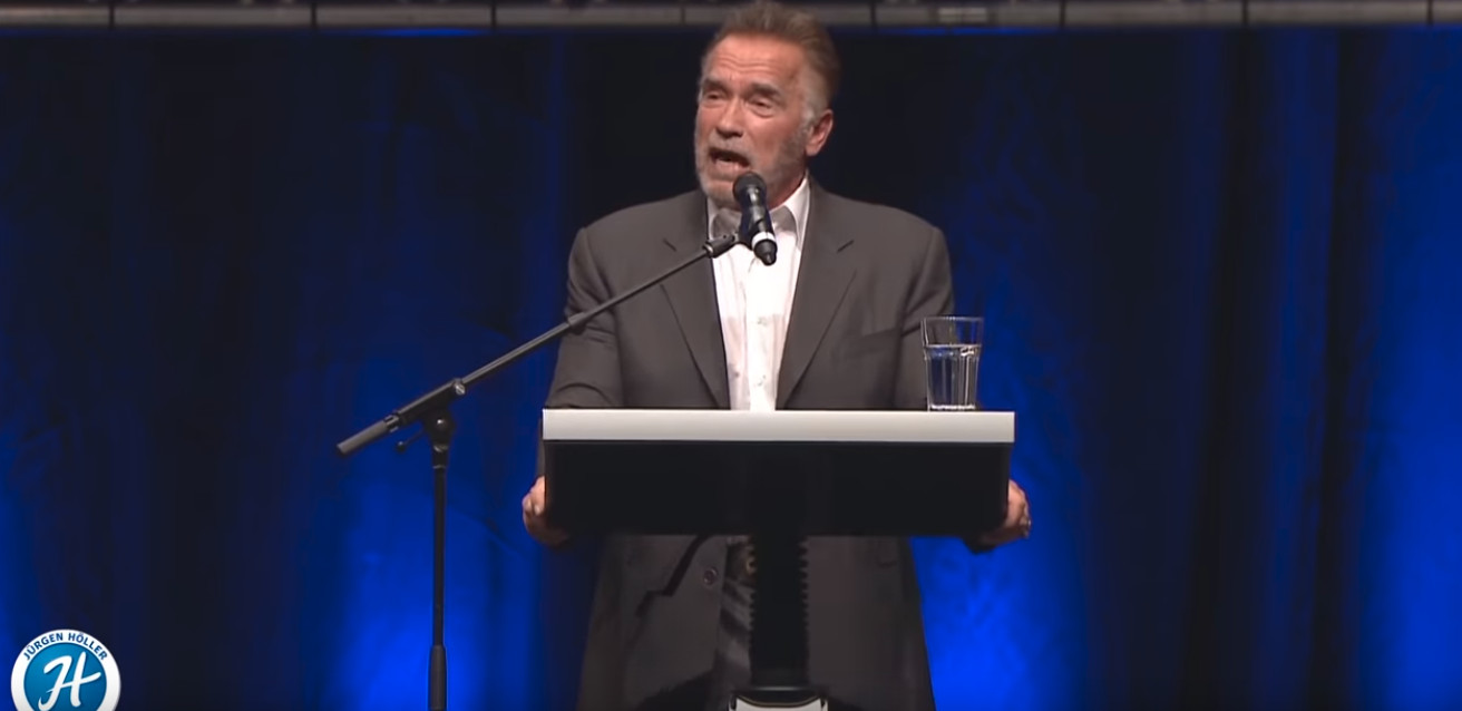
With the most inspiring speech by Arnold Schwarzenegger, 2019 arrived… I’ve got something in my mind as well…
Everybody has a dream/goal. NEVER EVER blow it out… Here comes the preface of my PhD’s thesis… It’s been 10 years already… This is NOT ONLY my attitude towards science, BUT ALSO towards those so-called professors(叫兽) and specialists(砖家).
So, today, I’m NOT going to repeat any cliches, BUT happily encouraged by Arnold Schwarzenegger’s speech. We will definitely have a fruitful 2019. Let’s have some pizza.
import cv2 import numpy as np import matplotlib.pyplot as plt import pydicom as pdicom import os import glob import pandas as pd import scipy.ndimage from skimage import measure, morphology from mpl_toolkits.mplot3d.art3d import Poly3DCollection
# Collect all dicom images lstFilesDCM = [] # create an empty list defload_scan2(path): for dirName, subdirList, fileList in os.walk(path): for filename in fileList: if".dcm"in filename.lower(): lstFilesDCM.append(os.path.join(dirName, filename)) return lstFilesDCM
first_patient = load_scan2(INPUT_FOLDER)
# Get ref file print (lstFilesDCM[0]) RefDs = pdicom.read_file(lstFilesDCM[0])
# Load dimensions based on the number of rows, columns and slices (along z axis) ConstPixelDims = (int(RefDs.Rows), int(RefDs.Columns), len(lstFilesDCM))
x = np.arange(0.0, (ConstPixelDims[0]+1)*ConstPixelSpacing[0], ConstPixelSpacing[0]) y = np.arange(0.0, (ConstPixelDims[1]+1)*ConstPixelSpacing[1], ConstPixelSpacing[1]) z = np.arange(0.0, (ConstPixelDims[2]+1)*ConstPixelSpacing[2], ConstPixelSpacing[2])
# loop through all the DICOM files for filenameDCM in lstFilesDCM: # read the file ds = pdicom.read_file(filenameDCM) # store the raw image data ArrayDicom[:, :, lstFilesDCM.index(filenameDCM)] = ds.pixel_array
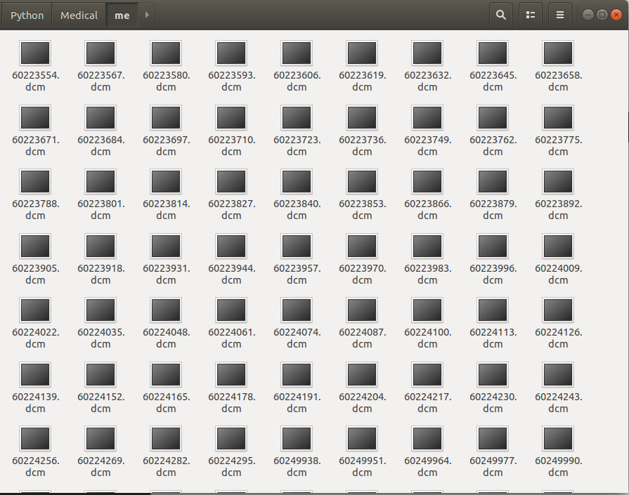
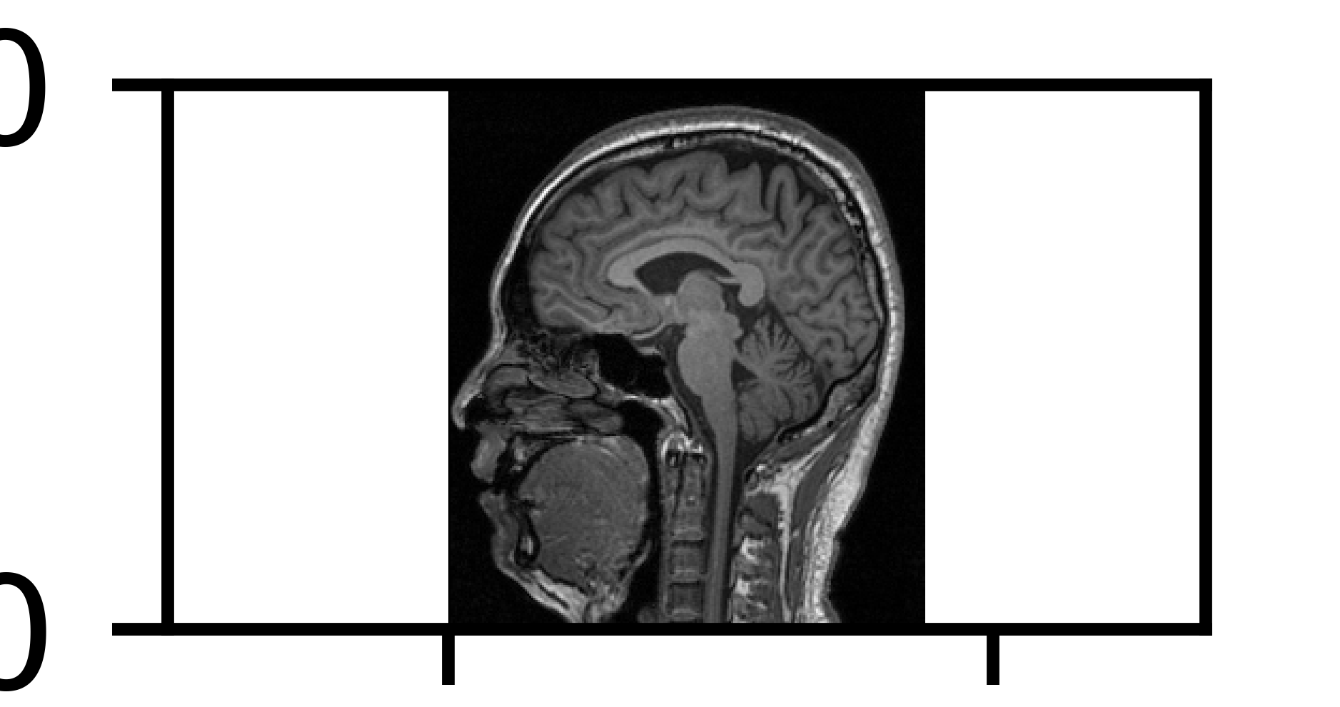
I did a MRI scan in 2015, in SIAT, for the purpose of research. The scan resolution is NOT very high. Anyway, a bunch of DICOM images can be viewed as follows:
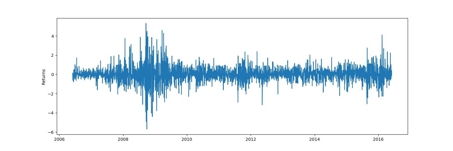
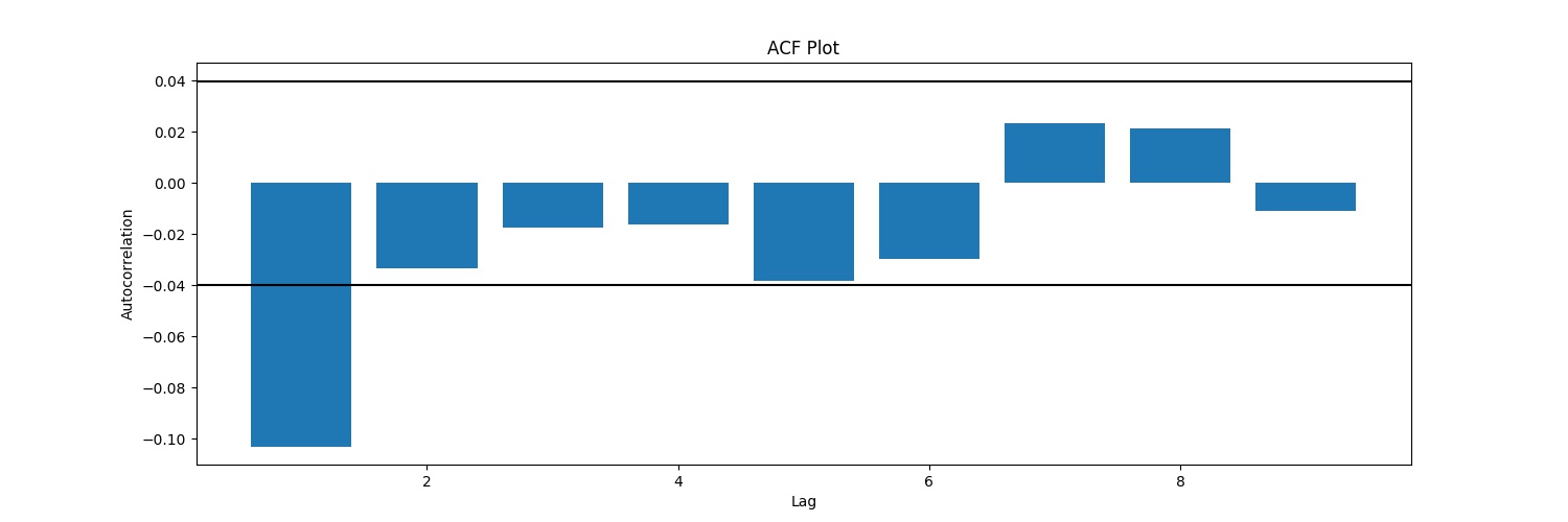
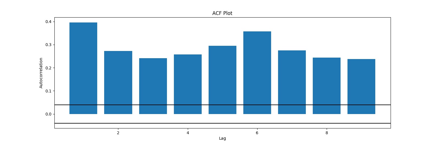
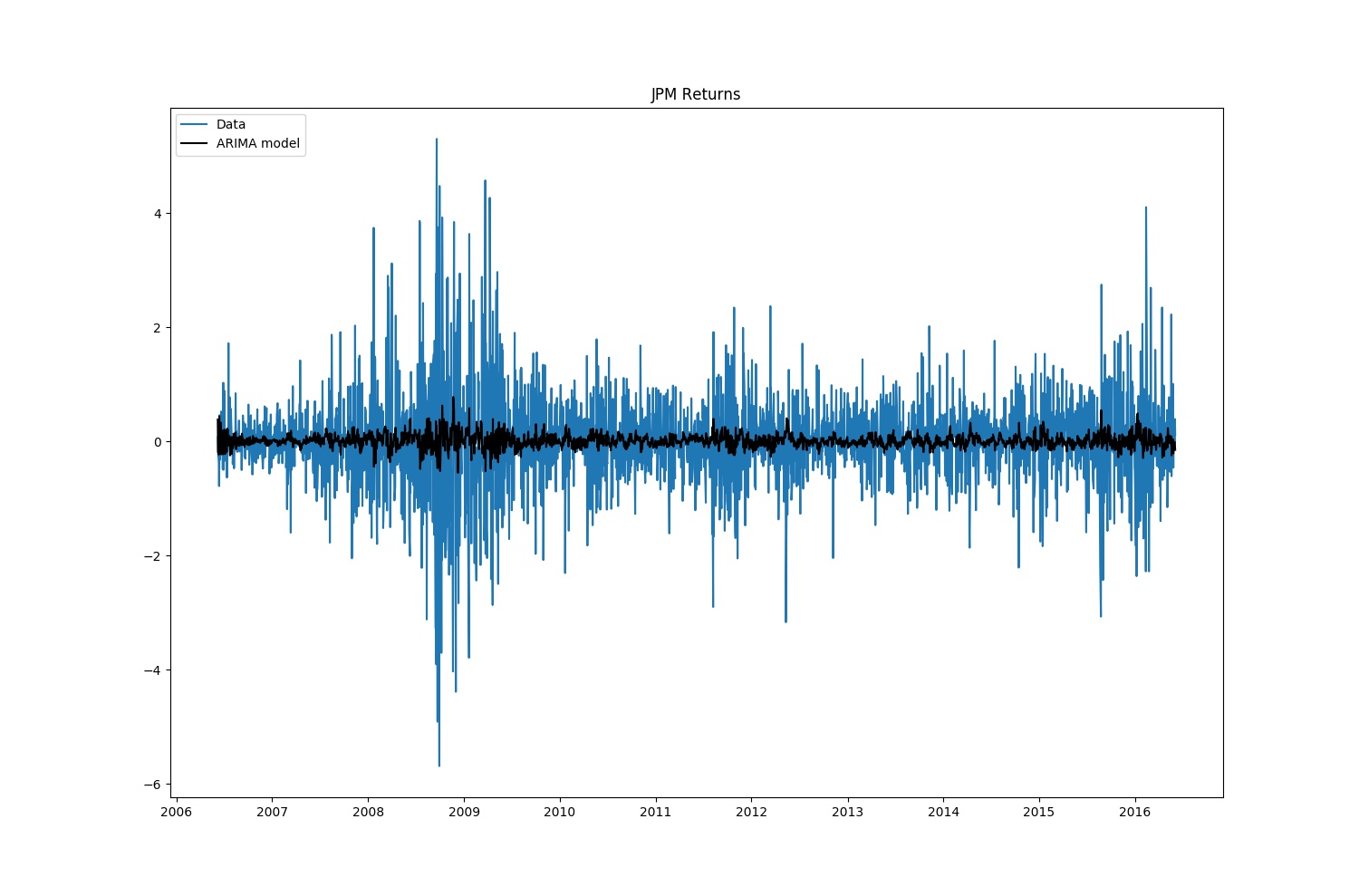
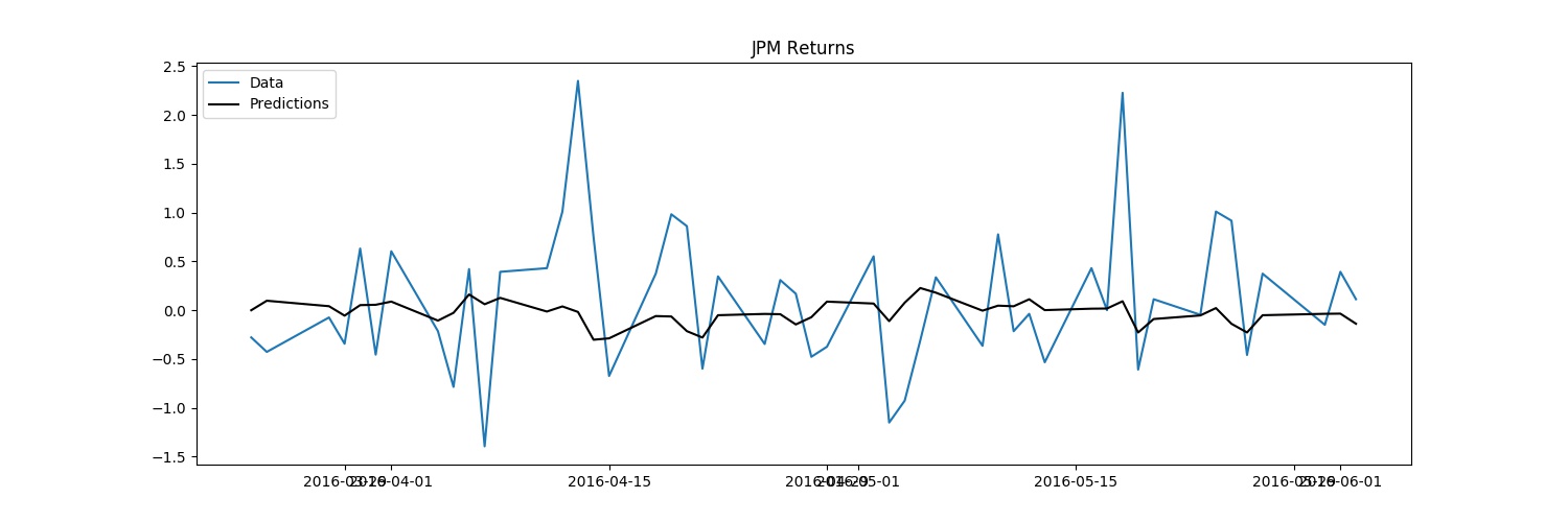
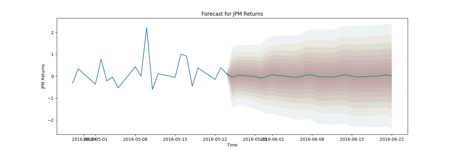
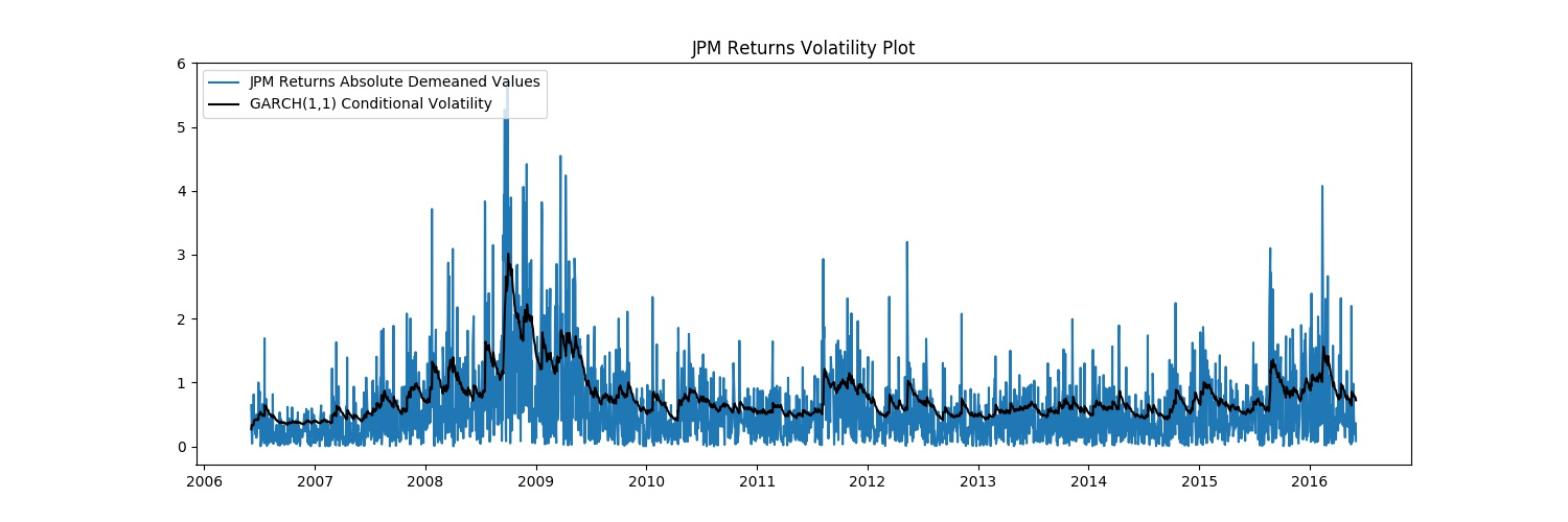
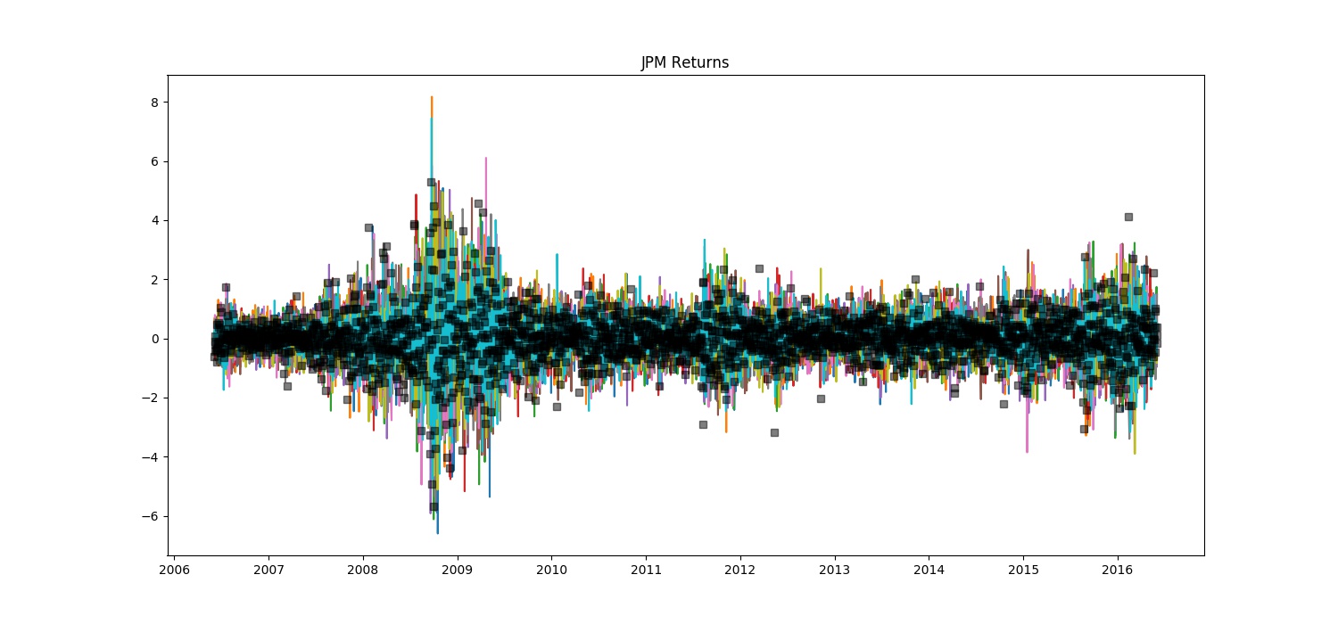
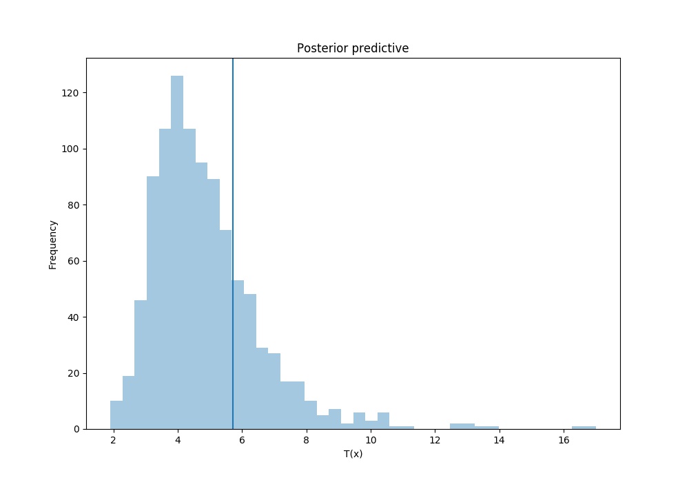
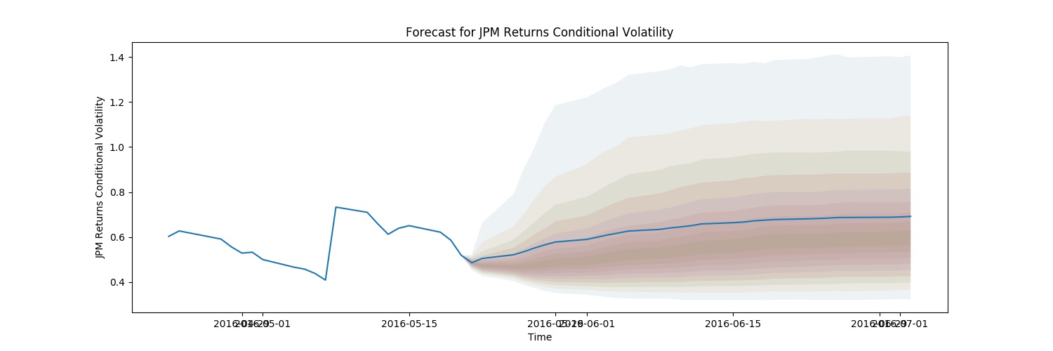
It’s been quite a while without writing anything. Today, we are going to introduce PyFlux for time seriers analysis. Cannonical models are to be directly adopted from PyFlux Documents and tested in this blog.
Get Started
Copy and paste that piece of code from PyFlux Documents with trivial modifications as follows:
import pandas as pd import numpy as np from pandas_datareader.data import DataReader from datetime import datetime import pyflux as pf import matplotlib.pyplot as plt
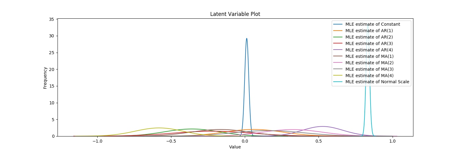
Index Latent Variable Prior Prior Hyperparameters V.I. Dist Transform ======== ========================= =============== ========================= ========== ========== 0 Constant Normal mu0: 0, sigma0: 3 Normal None 1 AR(1) Normal mu0: 0, sigma0: 0.5 Normal None 2 AR(2) Normal mu0: 0, sigma0: 0.5 Normal None 3 AR(3) Normal mu0: 0, sigma0: 0.5 Normal None 4 AR(4) Normal mu0: 0, sigma0: 0.5 Normal None 5 MA(1) Normal mu0: 0, sigma0: 0.5 Normal None 6 MA(2) Normal mu0: 0, sigma0: 0.5 Normal None 7 MA(3) Normal mu0: 0, sigma0: 0.5 Normal None 8 MA(4) Normal mu0: 0, sigma0: 0.5 Normal None 9 Normal Scale Flat n/a (non-informative) Normal exp
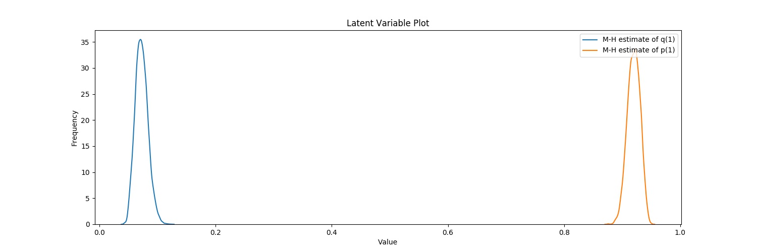
~/.local/lib/python3.6/site-packages/numdifftools/limits.py:126: UserWarning: All-NaN slice encountered warnings.warn(str(msg)) Acceptance rate of Metropolis-Hastings is 0.000125 Acceptance rate of Metropolis-Hastings is 0.00075 Acceptance rate of Metropolis-Hastings is 0.105525 Acceptance rate of Metropolis-Hastings is 0.13335 Acceptance rate of Metropolis-Hastings is 0.1907 Acceptance rate of Metropolis-Hastings is 0.232 Acceptance rate of Metropolis-Hastings is 0.299
Tuning complete! Now sampling. Acceptance rate of Metropolis-Hastings is 0.36655 GARCH(1,1) ======================================================= ================================================== Dependent Variable: JPM Returns Method: Metropolis Hastings Start Date: 2006-06-05 00:00:00 Unnormalized Log Posterior: -2671.5492 End Date: 2016-06-02 00:00:00 AIC: 5351.717896880396 Number of observations: 2517 BIC: 5375.041188860938 ========================================================================================================== Latent Variable Median Mean 95% Credibility Interval ======================================== ================== ================== ========================= Vol Constant 0.0059 0.0057 (0.004 | 0.0076) q(1) 0.0721 0.0728 (0.0556 | 0.0921) p(1) 0.9202 0.9199 (0.9013 | 0.9373) Returns Constant 0.0311 0.0311 (0.0109 | 0.0511) ==========================================================================================================
This blog is just to solve some bugs while using MySQL as a server. Assuming you’ve already installed mysql-server, mysql-server-5.7, and mysql-server-core-5.7.
1. Errors
1.1 Failed to start mysql.service: Unit mysql.service not found.
1 2 3 4 5 6 7
➜ ~ sudo service mysqld start [sudo] password for jiapei: Failed to start mysqld.service: Unit mysqld.service not found. ➜ ~ /etc/init.d/mysql stop [ ok ] Stopping mysql (via systemctl): mysql.service. ➜ ~ /etc/init.d/mysql start [ ok ] Starting mysql (via systemctl): mysql.service.
Conclusion: use /etc/init.d/mysql start instead of service mysqld start.
1.2 ERROR 1045 (28000): Access denied for user ‘root‘@’localhost’ (using password: YES)
1 2 3
➜ ~ mysql -u root -p Enter password: ERROR 1698 (28000): Access denied for user 'root'@'localhost'
We FIRST list all existing MySQL processes and kill them all.
1 2 3
➜ ~ ps aux | grep mysql ... ➜ ~ sudokill PID
Util now, there should be NO MySQL process running.
1.3 ERROR 2002 (HY000): Can’t connect to local MySQL server through socket ‘/var/run/mysqld/mysqld.sock’
Since there is NO MySQL process running, of course we cannot connect to MySQL server.
1 2 3 4 5 6 7
➜ ~ mysql -u root -p Enter password: ERROR 2002 (HY000): Can't connect to local MySQL server through socket '/var/run/mysqld/mysqld.sock' (2) ➜ ~ /etc/init.d/mysql start [....] Starting mysql (via systemctl): mysql.serviceJob for mysql.service failed because the control process exited with error code. See "systemctl status mysql.service" and "journalctl -xe" for details. failed!
Then, we will have to have these 3 packages reinstalled: mysql-server, mysql-server-5.7, and mysql-server-core-5.7.
/var/run/mysqld/mysqld.sock is NOW back, and MySQL seems to run automatically.
1 2 3 4 5
➜ ~ ls -ls /var/run/mysqld/mysqld.sock 0 srwxrwxrwx 1 mysql mysql 0 Nov 30 03:08 /var/run/mysqld/mysqld.sock ➜ ~ ps aux | grep mysql mysql 13785 0.1 0.3 1323300 172680 ? Sl 03:08 0:00 /usr/sbin/mysqld --daemonize --pid-file=/run/mysqld/mysqld.pid jiapei 14453 0.0 0.0 21556 2560 pts/0 R+ 03:16 0:00 grep --color=auto --exclude-dir=.bzr --exclude-dir=CVS --exclude-dir=.git --exclude-dir=.hg --exclude-dir=.svn mysql
Then, use chown and chmod to set up the owners and permissions suitably as follows.
1 2 3 4 5 6 7 8 9 10 11 12 13
➜ run pwd /var/run ➜ run sudochown mysql:mysql -R mysql ➜ run sudochmod 755 -R mysql ➜ run ls -lsd mysql 0 drwxr-xr-x 2 mysql mysql 100 Nov 30 02:38 mysqld ➜ run cd ../lib ➜ lib pwd /var/lib ➜ lib sudochown mysql:mysql -R mysql ➜ lib sudochmod 755 -R mysql ➜ lib ls -lsd mysql 4 drwxr-xr-x 6 mysql mysql 4096 Nov 30 02:38 mysql
1.4 ERROR 1698 (28000): Access denied for user ‘root‘@’localhost’
➜ ~ mysql -u root -p Enter password: ERROR 1698 (28000): Access denied for user 'root'@'localhost' ➜ ~ sudo mysql -u root Welcome to the MySQL monitor. Commands end with ; or \g. Your MySQL connection id is 3 Server version: 5.7.24-0ubuntu0.18.04.1 (Ubuntu)
Copyright (c) 2000, 2018, Oracle and/or its affiliates. All rights reserved.
Oracle is a registered trademark of Oracle Corporation and/or its affiliates. Other names may be trademarks of their respective owners.
Type 'help;' or '\h'forhelp. Type '\c' to clear the current input statement.
mysql> USE lvrsql; Reading table information for completion of table and column names You can turn off this feature to get a quicker startup with -A
Database changed mysql> CREATE USER 'YOUR_SYSTEM_USER'@'localhost' IDENTIFIED BY 'YOUR_PASSWORD'; mysql> GRANT ALL PRIVILEGES ON *.* TO 'YOUR_SYSTEM_USER'@'localhost'; mysql> FLUSH PRIVILEGES; mysql> exit;
➜ ~ service mysql restart ➜ ~
1.5 [ERROR] InnoDB: Unable to lock ./ibdata1 (Additional)
If you meet the above ERROR message, what you can do is to restart MySQL by:
1
2
3
➜  ~ /etc/init.d/mysql restart
[ ok ] Restarting mysql (via systemctl): mysql.service.
➜  ~
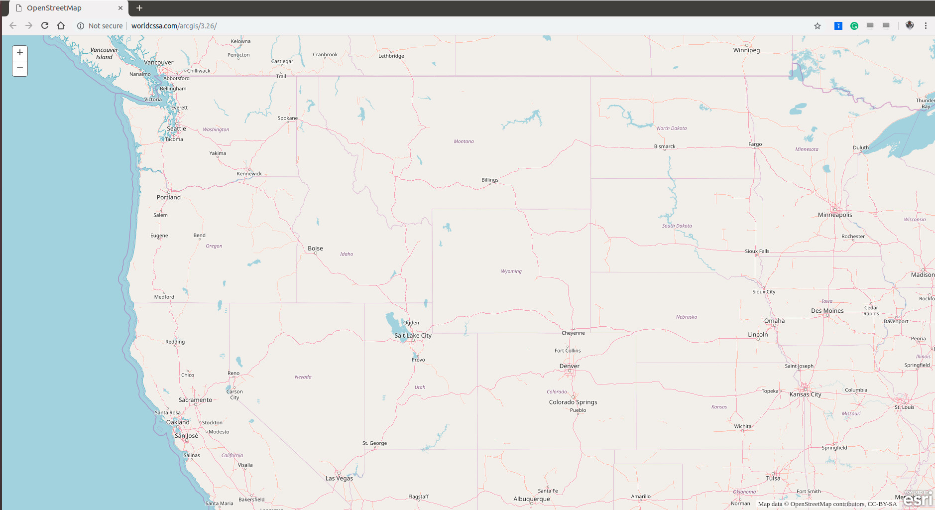
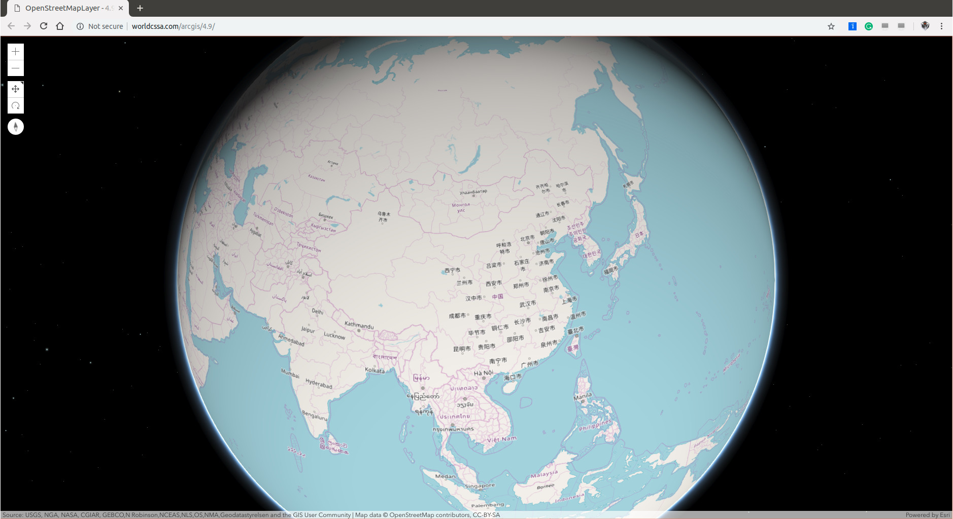
var view = new SceneView({ map: map, container: "viewDiv" });
var osmLayer = new OpenStreetMapLayer(); map.add(osmLayer); }); </script> </head>
<body> <div id="viewDiv"></div> </body>
</html>
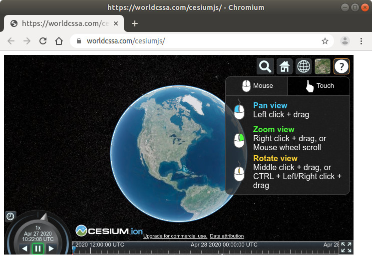
Please click on the following image and have a try.
ArcGIS is like the CROWN of GIS. Its SDK/API seems NOT fully open source but commercial. Therefore, I’d love to breifly test out some other open source.
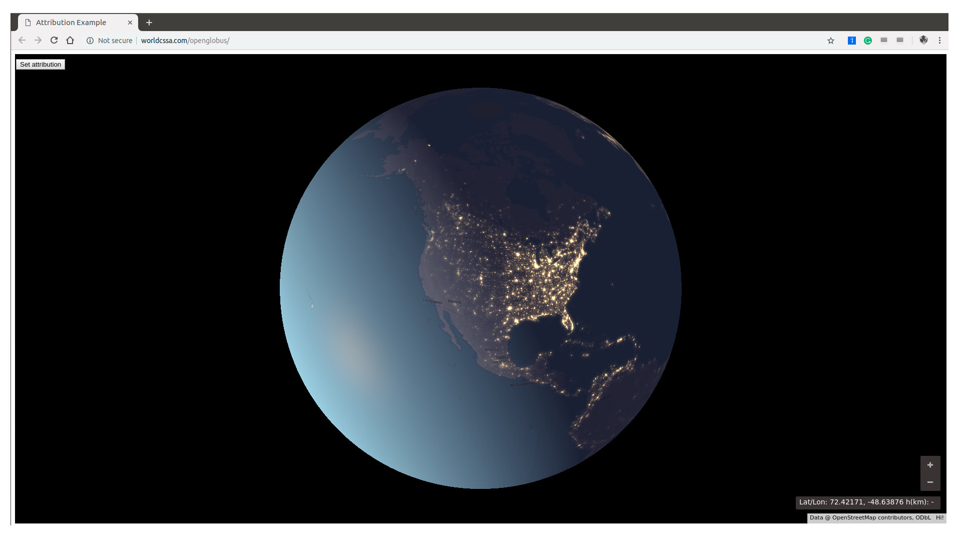
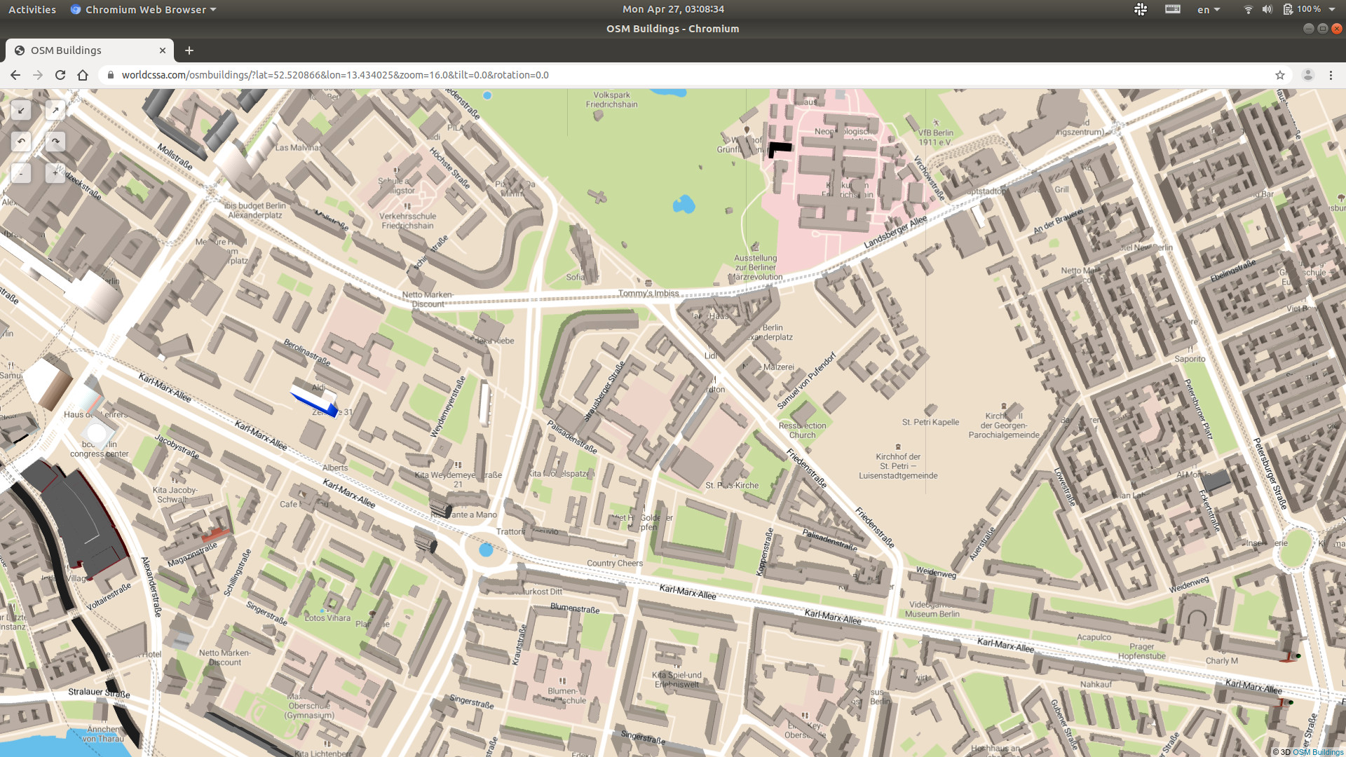
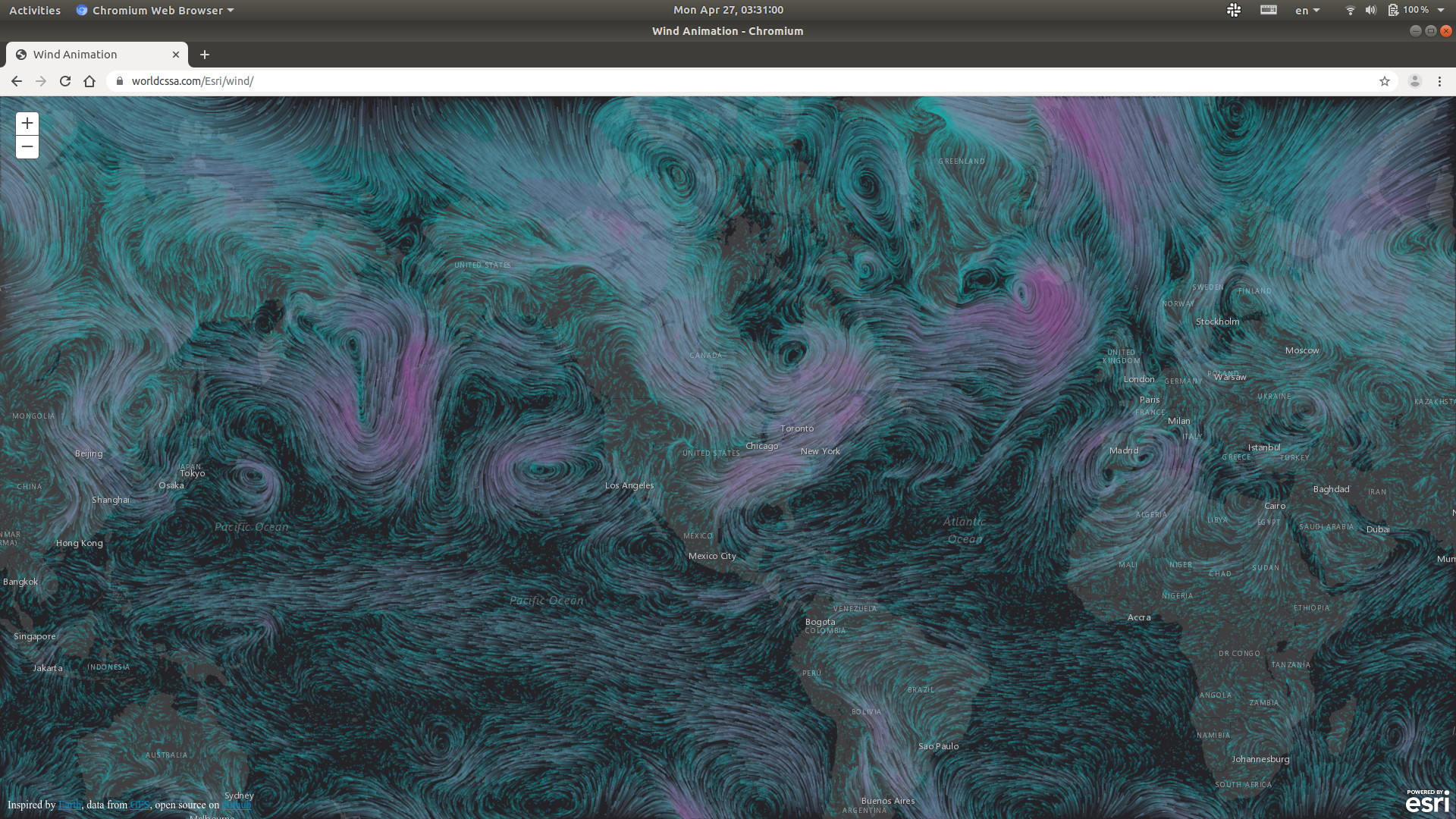
“OpenGlobus is a javascript library designed to display interactive 3d maps and planets with map tiles, imagery and vector data, markers and 3d objects. It uses the WebGL technology, open source and completely free.” (Cited from OpenGlobus Github). Let’s just take the very FIRST example Og - examples: Attribution as our example. Code is cited as follows:
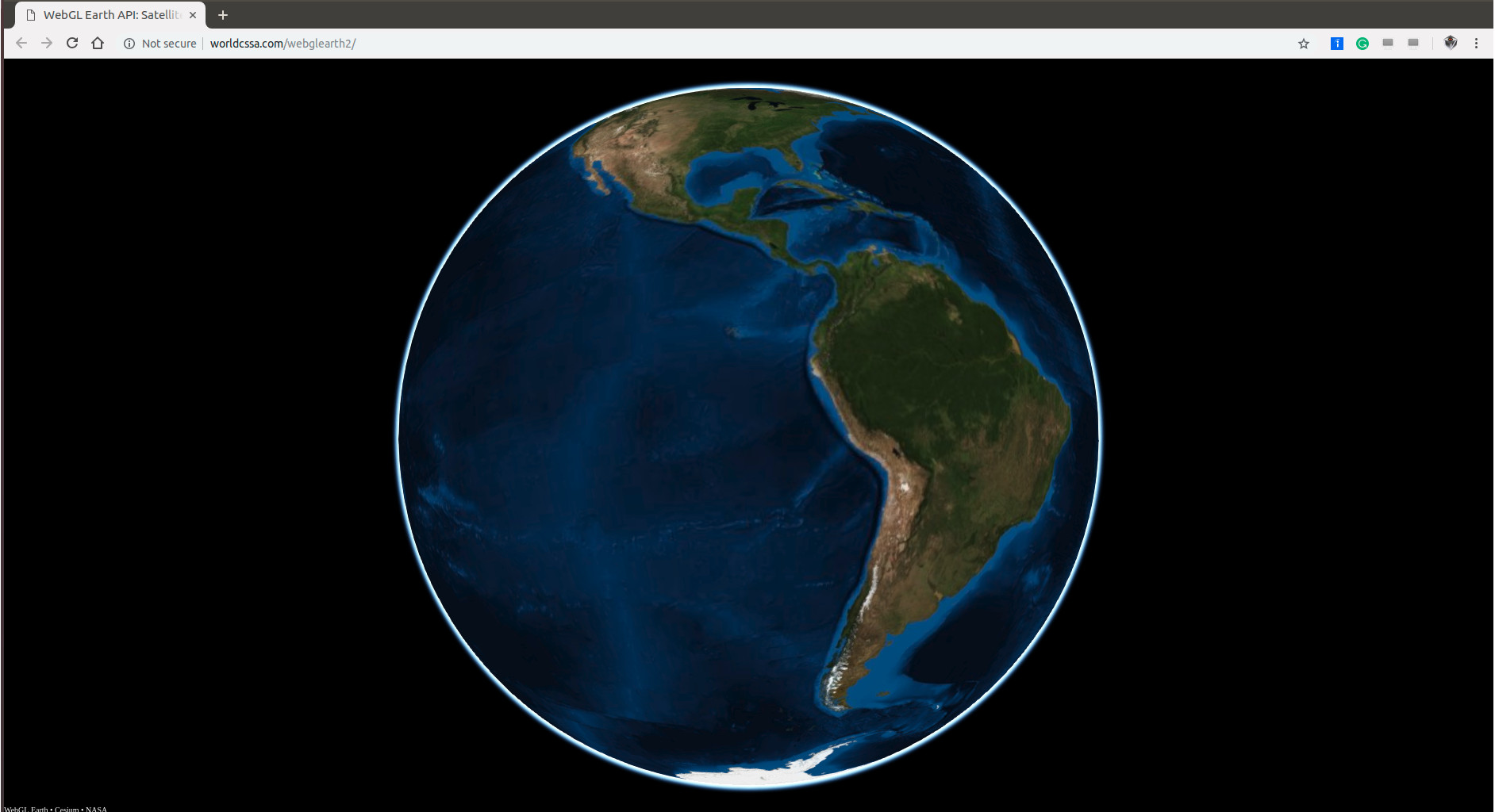
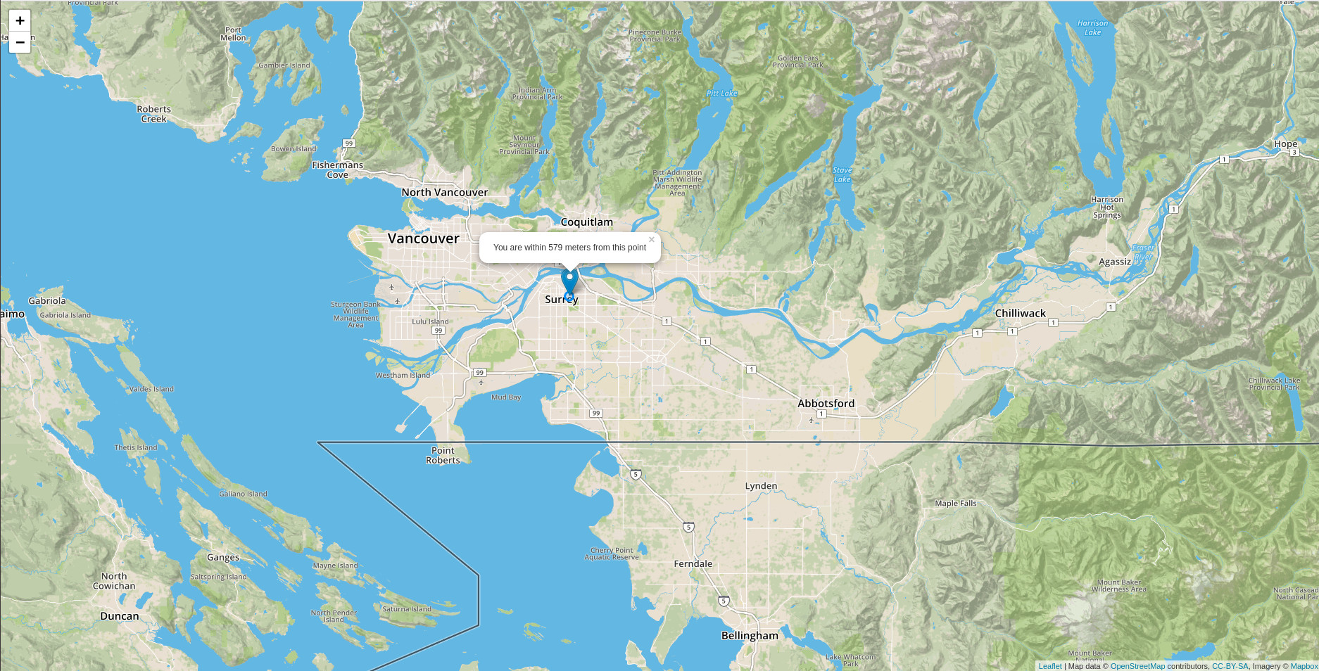
OpenStreetMap may be covered by different tiles in order to show different maps. For instance, Google map vs Google satellite map. Let’s take a look at Home Page of WebGLEarth, you’ll notice MapTiler at the left bottom corner. Here, we summarize 3 widely used tiles in the following:
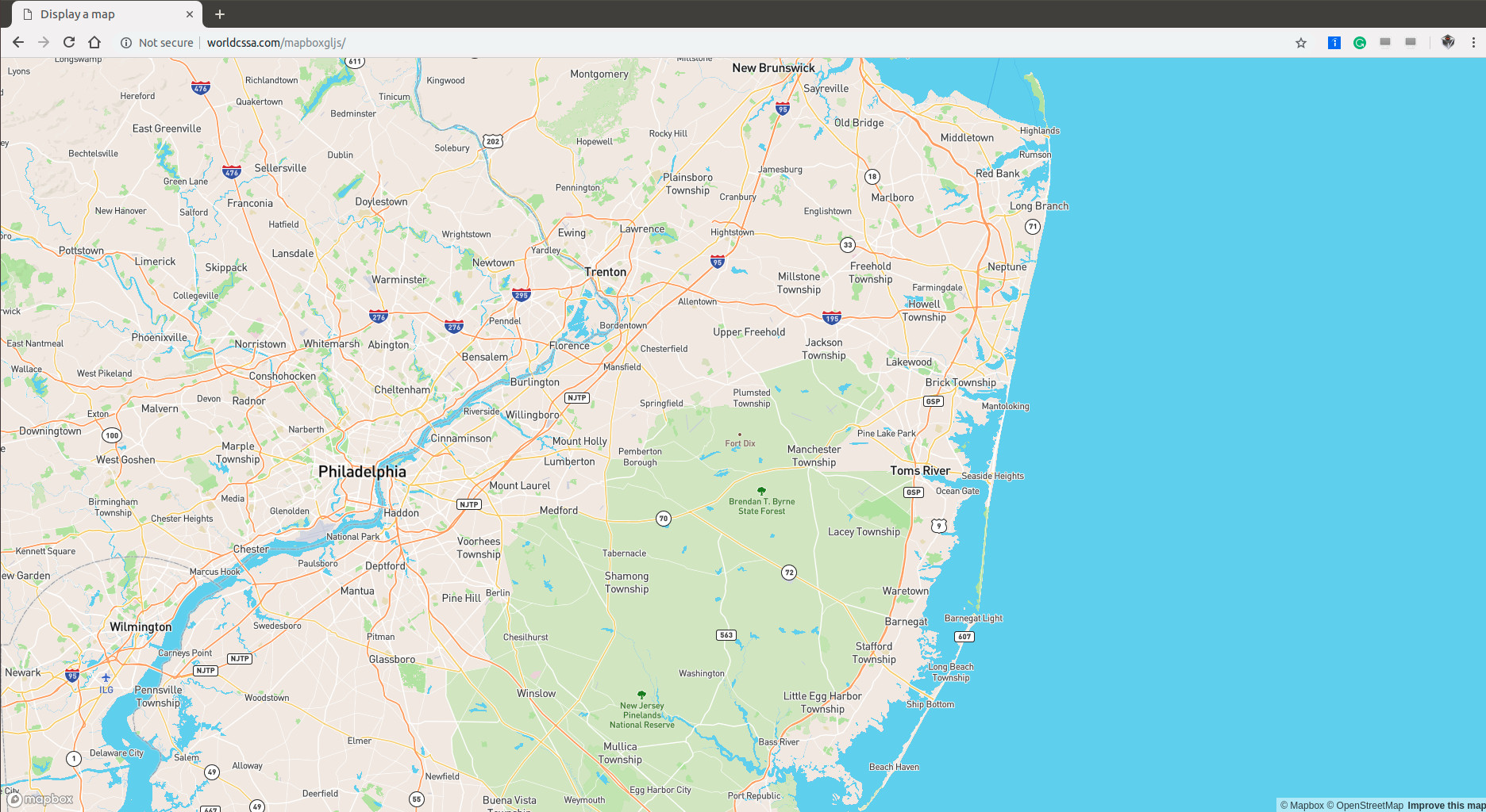
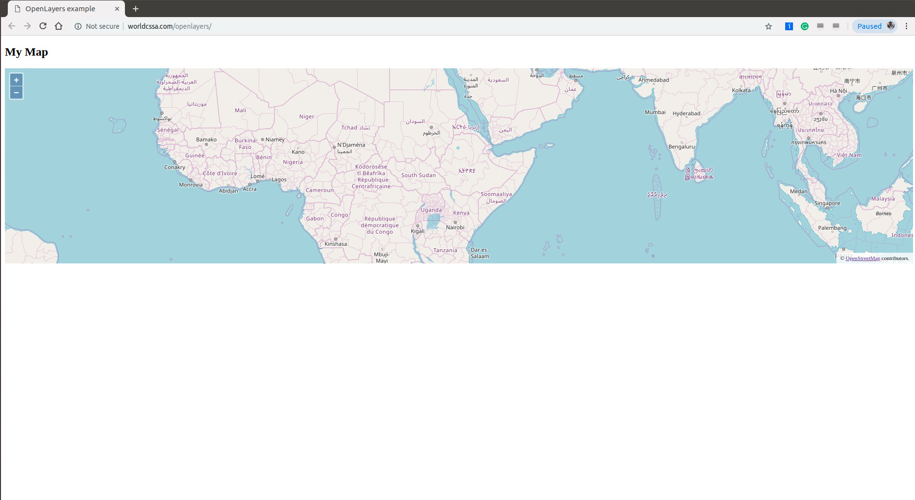
Besides tiles, there might be several layers (including one layer of tile) upon OpenStreetMap, here comes OpenLayers: “OpenLayers makes it easy to put a dynamic map in any web page. It can display map tiles, vector data and markers loaded from any source.” (cited from https://openlayers.org/)
Yesterday, we briefly introduced Quantopian and how to ingest Quandl WIKI Bundle data. Today, we are going to briefly summarize the financial data source and how to retrieve Google and Yahoo finance data using pandas_datareader.
# Define the instruments to download. We would like to see Apple, Microsoft and the S&P500 index.
tickers = ['AAPL', 'MSFT', '^GSPC']

# We would like all available data from 01/01/2017 until 12/31/2017.
start_date = '2017-01-01'
end_date = '2017-12-31'
df = data.DataReader(tickers, data_source='google', start=start_date, end=end_date)
Exception has occurred: pandas_datareader.exceptions.ImmediateDeprecationError
Google finance has been immediately deprecated due to large breaks in the API without the introduction of a stable replacement. Pull Requests to re-enable these data connectors are welcome. See https://github.com/pydata/pandas-datareader/issues
File "....../test.py", line 16, in
df = data.DataReader(tickers, data_source='google', start=start_date, end=end_date)
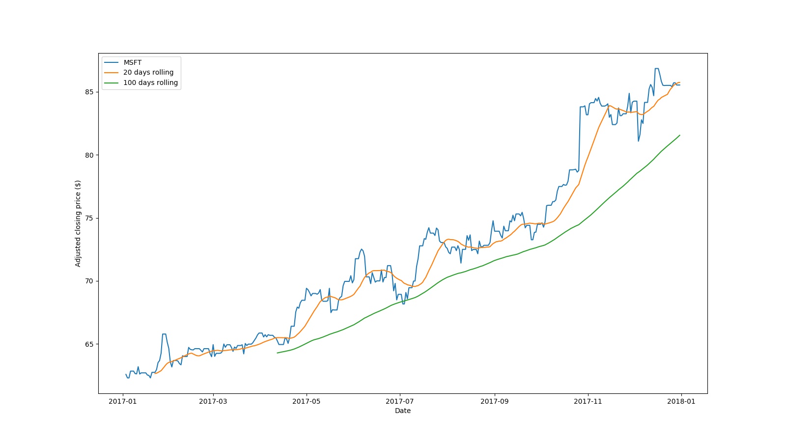
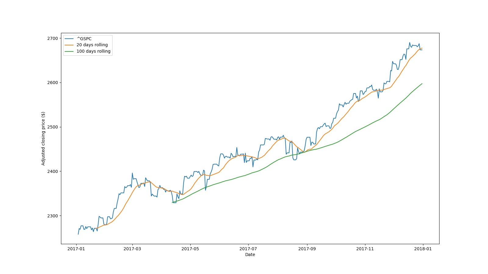
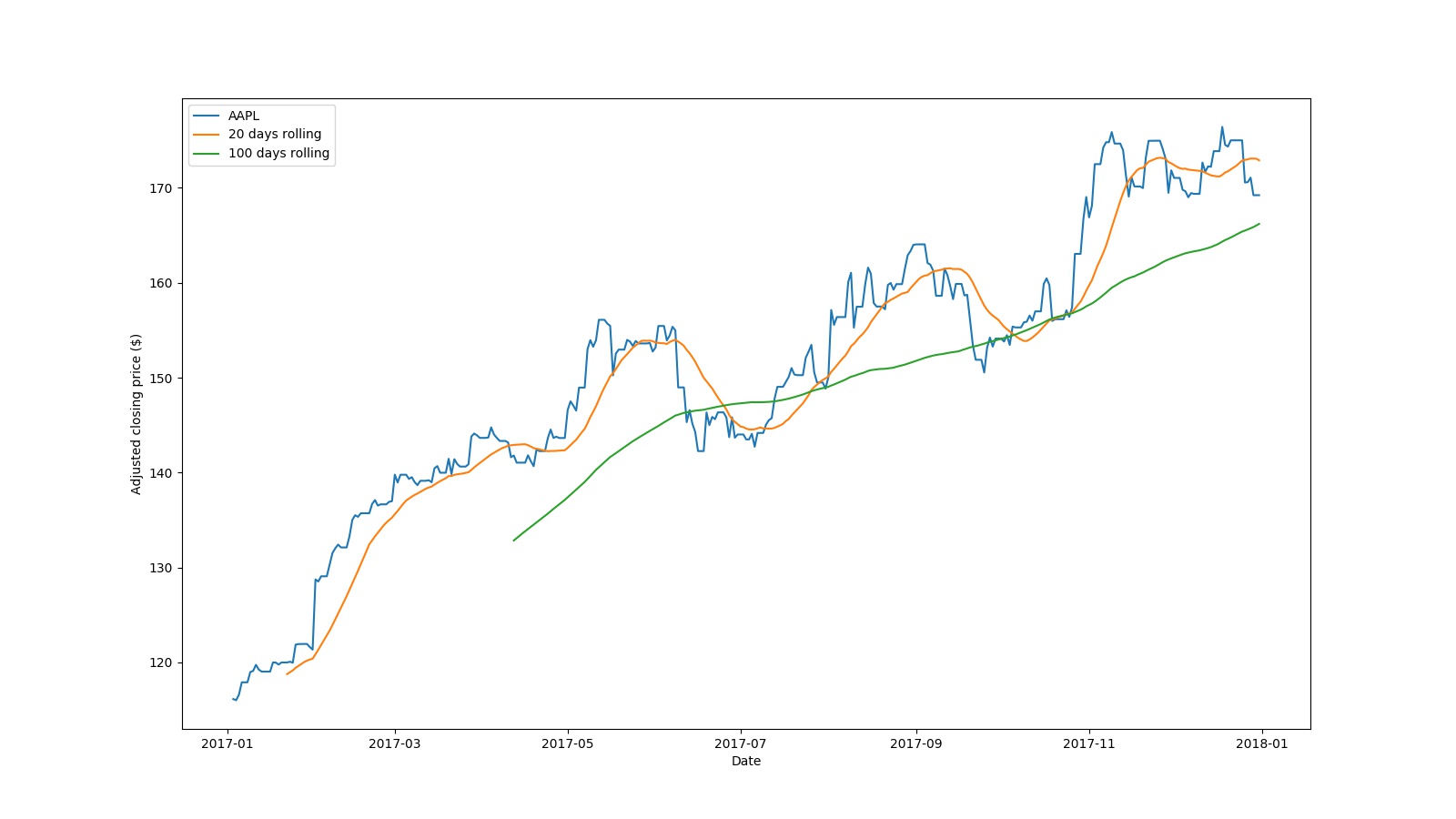
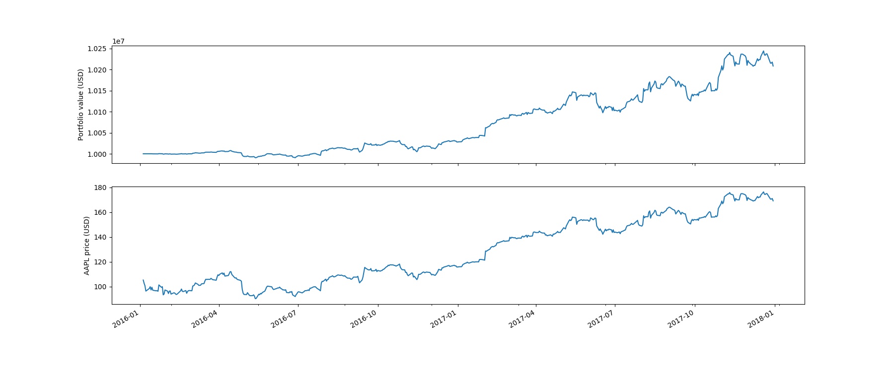
On the other hand, from the following 3 finance data resource, the following printed tables and generated pictures demonstrate that stock data can be successfully loaded.
# Define the instruments to download. We would like to see Apple, Microsoft and the S&P500 index.
tickers = ['AAPL', 'MSFT', '^GSPC']

# We would like all available data from 01/01/2017 until 12/31/2017.
start_date = '2017-01-01'
end_date = '2017-12-31'
df = data.DataReader(tickers, data_source='yahoo', start=start_date, end=end_date)
# Define the instruments to download. We would like to see Apple, Microsoft and the S&P500 index.
tickers = ['AAPL', 'MSFT', 'SPY']

# We would like all available data from 01/01/2017 until 12/31/2017.
start_date = '2017-01-01'
end_date = '2017-12-31'
df = data.DataReader(tickers, data_source="iex", start=start_date, end=end_date)
# We would like all available data from 01/01/2017 until 12/31/2017.
start_date = '2017-01-01'
end_date = '2017-12-31'
df = data.DataReader('AAPL', data_source="quandl", start=start_date, end=end_date, access_key="your-quandl-api-key")
# df = data.DataReader('MSFT', data_source="quandl", start=start_date, end=end_date, access_key="your-quandl-api-key")
Today, let’s have some fun of AI in finance. We are going to use a tool named Quantopian. As far as I know, functional programming language Haskell has been widely used in quantitative analysis. That’s possibly why a dependent package of Quantopian, namely pandoc, requires The Haskell Tool Stack for its installation. Therefore, Haskell and pandoc need to be installed before Quantopian installation.
As known, Quantopian is a Python collections of various quantitative analysis algorithms. However, where can we obtain the stock data for our testing? Either the real-time data, or the historical data will do.
➜  quantopian QUANDL_API_KEY=<yourkey> zipline ingest -b quandl
[2018-11-07 05:18:37.895463] INFO: zipline.data.bundles.quandl: Downloading WIKI metadata.
Downloading WIKI Prices table from Quandl  [####################################]  100%
[2018-11-07 05:18:54.369791] INFO: zipline.data.bundles.quandl: Parsing raw data.
[2018-11-07 05:19:24.118879] INFO: zipline.data.bundles.quandl: Generating asset metadata.
Merging daily equity files:  [-----------------------------#------]  1731~/.local/lib/python3.6/site-packages/zipline/data/us_equity_pricing.py:417: UserWarning: Ignoring 1 values because they are out of bounds for uint32:             open  high   low  close        volume  ex_dividend  split_ratio
2011-04-11  1.79  1.84  1.55    1.7  6.674913e+09          0.0          1.0
  winsorise_uint32(raw_data, invalid_data_behavior, 'volume', *OHLC)
Merging daily equity files:  [####################################]
[2018-11-07 05:21:34.367628] INFO: zipline.data.bundles.quandl: Parsing split data.
[2018-11-07 05:21:34.572459] INFO: zipline.data.bundles.quandl: Parsing dividend data.
~/.local/lib/python3.6/site-packages/zipline/data/us_equity_pricing.py:931: FutureWarning: Conversion of the second argument of issubdtype from `float` to `np.floating` is deprecated. In future, it will be treated as `np.float64 == np.dtype(float).type`.
  if not issubdtype(actual, expected):
➜  quantopian